
Summary Highlights
- Importance of unit protection relay maintenance: ensuring reliable protection of generators, transformers and connected equipment against internal faults
- Basic maintenance steps: visual inspection, setting verification, secondary injection, differential and auxiliary function tests, trip circuit check
- Main checks to be performed: CT-VT chain, polarity and ratio verification, differential characteristic, earth fault and overcurrent functions, voltage and frequency protections
- Advanced verifications: harmonic restraint, binary input-output test, oscillography and event record review, communication and time synchronization check
- Recording and trend tracking: comparison of trip times, pickup results, alarm history, setting revisions and maintenance reports
Article Details
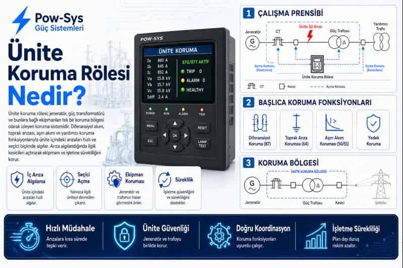
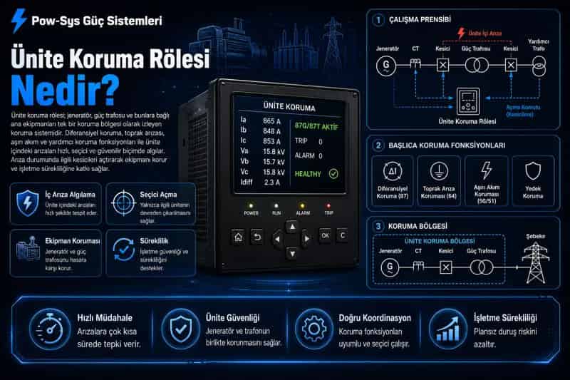
Unit protection relays are among the most critical protection devices in systems where a generator, power transformer and connected auxiliary equipment are protected together. Therefore, the tests and maintenance required for unit protection relays are not performed only to verify that the device appears to be operating. The main purpose is to verify that the relay correctly detects faults inside the protection zone, remains stable during external faults, that auxiliary protection functions behave as expected and that the trip chain operates completely. Since these relays protect high-power and high-cost equipment, even a small setting or connection error can cause major damage.
The first step of maintenance is always safety. Before working on a unit protection relay, the related generation or transformation unit should be placed in a safe test condition, test blocks should be used correctly and CT-VT secondary circuits should be managed in a controlled way. Especially in systems with differential protection logic, preparation before testing is much more important because multiple current inputs are used together. An incorrectly isolated secondary circuit or faulty test connection can create a greater field risk than a relay fault.
Visual inspection is the basis of maintenance. The relay front panel, display, LED indicators, alarm records, self-supervision warnings, terminal connections, communication ports, auxiliary supply terminals and binary input-output modules should be visually inspected. If the relay has signals such as internal fault alarm, memory warning, time synchronization loss, measurement circuit alarm or input-output fault, these should become maintenance priorities. Modern numerical relays often show the first sign of field problems in their own alarm list.
One of the first technical steps in unit protection relay maintenance is setting verification. The active setting file loaded in the relay should be compared with the approved protection file. Generator and transformer data, CT ratios, VT ratios, vector group definitions, differential curve settings, harmonic restraint values, earth fault and overcurrent stages, voltage and frequency functions, reverse power or negative sequence auxiliary protection settings should be compatible with project data. Even a small setting change made in the field can affect the entire protection logic.
Secondary injection testing is the basic method of periodic maintenance. In this test, controlled current and voltage signals are applied to the relay to verify whether both main and auxiliary protection functions operate correctly. In unit protection relays, this is not limited to seeing that the relay trips. Pickup level, time behavior, differential operate logic and whether auxiliary functions are activated under expected conditions should also be checked.
One of the most critical subjects in unit protection relays is differential protection testing. It should be verified that the relay correctly compares the currents entering and leaving the protection zone, operates quickly for internal fault scenarios and remains stable under external fault conditions. In these tests, not only the operate point but also the restraint behavior should be examined. A good unit protection relay should detect an internal fault quickly and should not trip incorrectly during an external fault or temporary imbalance.
Differential characteristic testing is the core of maintenance. In current scenarios representing internal faults, it should be checked that the relay operates in the expected operating region; in scenarios representing the restraint region, it should be checked that it does not trip. If the relay trips earlier than expected at the stability boundary, unnecessary trip risk arises during external faults. If it trips too late, protection is delayed during a real internal fault. Therefore, field verification of the differential curve is mandatory.
The CT and VT chain is one of the most critical field subjects in these systems. CT polarity, ratios, phase sequence, secondary circuit continuity and grounding points directly affect the relay decision. In VT circuits, the ratio, phase sequence and secondary connection logic should also be verified. A unit protection relay needs correct voltage and current information not only for differential current but also for many auxiliary functions. An error in the measurement chain can cause the entire protection system to operate incorrectly.
In applications such as a generator-transformer unit, vector group and phase compensation should also be checked separately. If the transformer connection group is not defined correctly, the relay may see false differential current even under normal load. Therefore, during testing, not only current magnitude but also phase relationships and compensation logic should be verified. Correct current value alone is not sufficient; phase angle compatibility is equally important.
In systems with harmonic restraint or inrush security, these functions should also be tested separately. Especially during transformer energization or transient events caused by magnetic behavior, the relay must not behave as if there is an internal fault. Therefore, second harmonic blocking, restraint logic or related advanced functions should be included in the test plan. If the unit protection relay trips incorrectly under these conditions, a serious continuity problem occurs in real operation.
Auxiliary protection functions should also be verified one by one. Overcurrent, earth fault, overvoltage, undervoltage, frequency, reverse power, negative sequence current and any special protection functions related to the rotor or stator should be checked separately. A unit protection relay is often multifunctional, and these auxiliary functions are as important as the main differential protection for operational safety. Therefore, maintenance should not be reduced only to the main protection test.
Trip circuit and binary input-output tests are indispensable parts of maintenance. It is not enough for the relay to make the correct decision; that decision must reach the related breaker or breakers completely. Especially in unit protection applications, the generator side, transformer side and in some cases additional trip chains may operate together. Therefore, trip outputs, interposing relays, binary inputs, blocking logic and alarm contacts should be verified one by one.
Event records and oscillography review are important parts of maintenance. Event records can show from which function the relay picked up in the past, under which condition it tripped, how differential events and auxiliary protection alarms occurred and the timing of the trip chain. Especially if unexpected trips, meaningless alarm records or unexplained instability exist, these records directly guide the maintenance plan.
Communication and time synchronization should also be checked. If SCADA, IEC 61850, the central recording system, oscillography transfer and time synchronization infrastructure do not operate properly, event analysis and station automation become weaker. In a relay with incorrect time information, correctly analyzing the fault sequence becomes difficult. Therefore, in modern unit protection relay maintenance, the data chain should also be considered part of the protection chain.
At the end of maintenance, all results should be recorded. Which differential test points were applied, harmonic restraint result, auxiliary protection pickup values, binary output verifications, CT-VT check findings, alarm history and setting revisions should be archived regularly. Unit protection problems often grow not suddenly but through measurement chain deviation, setting changes or small unrecorded instabilities. If trend tracking is performed, weak points can be seen before real equipment damage occurs. In summary, the tests and maintenance required for unit protection relays require safe test preparation, setting verification, secondary injection, differential and auxiliary protection tests, CT-VT and compensation verification, harmonic restraint check, trip circuit testing and event record analysis to be carried out together. This approach is the most important verification showing that the main protection of the high-power equipment group is truly ready for duty.
Related Blog Posts
Related Services
Frequently Asked Questions
Why is maintenance required on unit protection relays?
Maintenance is required because unit protection relays are among the most critical protection devices in systems where a generator, power transformer and connected auxiliary equipment are protected together. Maintenance is not performed only to verify that the device appears to be operating; the main purpose is to confirm that the relay correctly detects faults inside the protection zone, remains stable during external faults, that the auxiliary protection functions behave as expected and that the trip chain operates completely. Since these relays protect high-power and high-cost equipment, even a small setting or connection error can cause major damage. A weakness in the settings, the CT-VT chain, the compensation logic or the trip circuit can undermine protection even when the relay itself looks healthy. Regular maintenance verifies differential sensitivity, the auxiliary functions and the trip chain together, so that the main protection of the high-power equipment group stays ready for duty.
Which tests are performed on unit protection relays?
Setting verification, secondary injection, differential characteristic testing, auxiliary protection function tests, CT-VT chain checks, harmonic restraint verification and trip circuit tests can be performed. Setting verification compares the active setting file with the approved protection file, checking generator and transformer data, CT and VT ratios, vector group definitions, differential curve settings, harmonic restraint values, earth fault and overcurrent stages, voltage and frequency functions and any reverse power or negative sequence settings. Secondary injection applies controlled current and voltage to confirm that both the main and auxiliary functions operate. Differential characteristic testing checks correct operation for internal faults and stability for external ones, and vector group and phase compensation are verified. The overcurrent, earth fault, voltage, frequency, reverse power and negative sequence functions are tested one by one, and the CT-VT chain, harmonic restraint, trip circuit, binary inputs and outputs and event records are checked. The scope depends on the relay's function set.
Why is secondary injection the basic test method?
Secondary injection is the basic test method because it allows the relay's measurement and decision chain to be verified safely, and it shows whether both the main and auxiliary functions operate under the expected conditions. In this test, controlled current and voltage signals are applied to the relay to check whether the protection functions behave correctly. In unit protection relays, this is not limited to seeing that the relay trips; the pickup level, the time behavior, the differential operate logic and whether the auxiliary functions are activated under the expected conditions should all be checked. By injecting known signals, maintenance can confirm the relay interprets faults as intended without waiting for a real fault on the generator or transformer. Because a unit protection relay is usually multifunctional, secondary injection is what makes it possible to exercise each function individually and safely.
What does the differential test verify?
The differential test verifies that the relay operates for current scenarios representing faults inside the unit and remains stable under conditions representing external faults. Differential protection testing is one of the most critical subjects in unit protection relays: it should be confirmed that the relay correctly compares the currents entering and leaving the protection zone, operates quickly for internal fault scenarios and stays stable during external faults or temporary imbalance. In these tests, not only the operate point but also the restraint behavior should be examined. This is refined by differential characteristic testing, where the relay is expected to operate in the internal-fault region and not to trip in the restraint region. If the relay trips earlier than expected at the stability boundary, unnecessary trip risk arises during external faults, and if it trips too late, protection is delayed during a real internal fault. For this reason field verification of the differential curve is treated as mandatory.
Why are the CT and VT chains checked separately?
The CT and VT chains are checked separately because incorrect ratios, reversed polarity or phase relationship errors can disrupt the entire decision logic of the relay. The CT and VT chain is one of the most critical field subjects in these systems: CT polarity, ratios, phase sequence, secondary circuit continuity and grounding points directly affect the relay decision, and in the VT circuits the ratio, phase sequence and secondary connection logic should also be verified. A unit protection relay needs correct voltage and current information not only for the differential current but also for many auxiliary functions, so an error in the measurement chain can cause the entire protection system to operate incorrectly. Measurement chain accuracy is especially critical in differential protection, where a CT polarity or ratio error can produce false differential current even under normal load.
Why is the harmonic restraint test important?
The harmonic restraint test is important because during transformer energization or magnetic transient events, the relay must not incorrectly trip by interpreting the condition as an internal fault. In systems with harmonic restraint or inrush security, these functions should be tested separately, because the transient current that appears during energization or magnetic behavior can look like a differential current. For this reason second harmonic blocking, restraint logic or related advanced functions should be included in the test plan, so that the relay stays put during these conditions while still being ready to trip for a real internal fault. If the unit protection relay trips incorrectly under these conditions, a serious continuity problem occurs in real operation, since the unit could be disconnected simply for being energized. Correct operation of this function is therefore important for continuity of operation, and verifying it is part of confirming that the relay distinguishes normal transient behavior from a genuine fault inside the protection zone.
Should auxiliary protection functions also be tested?
Yes, auxiliary protection functions should also be tested, and they must be verified one by one. A unit protection relay is often multifunctional, and functions such as overcurrent, earth fault, overvoltage, undervoltage, frequency, reverse power, negative sequence current and any special functions related to the rotor or stator should be checked separately. These auxiliary functions are as important as the main differential protection for operational safety, so maintenance should not be reduced only to the main protection test. Because each of these functions guards against a different abnormal condition of the generator, transformer and connected equipment, a fault or wrong setting in any of them can leave part of the unit unprotected even when the differential function is healthy. Testing them individually, with secondary injection to confirm their pickup levels and time behavior under the expected conditions, ensures that the full protection function of the relay is ready, not just its core differential element.
Why is the trip circuit test considered critical?
The trip circuit test is considered critical because it is not enough for the relay to make the correct decision; that decision must reach the related breaker or breakers completely. Especially in unit protection applications, the generator side, the transformer side and in some cases additional trip chains may operate together, so there is more than one path to confirm. For this reason the trip outputs, interposing relays, binary inputs, blocking logic and alarm contacts should be verified one by one, and trip circuit and binary input-output tests are indispensable parts of maintenance. Even if the relay decides correctly and its differential and auxiliary functions are healthy, the real protection function does not occur if the trip chain is faulty, because the equipment would not actually be disconnected.
Why are event records examined during maintenance?
Event records are examined because past pickup, trip, alarm and instability events provide very valuable information about the real field behavior of the relay. During maintenance, event records and oscillography can show from which function the relay picked up in the past, under which condition it tripped, how differential events and auxiliary protection alarms occurred, and the timing of the trip chain. Especially if unexpected trips, meaningless alarm records or unexplained instability exist, these records directly guide the maintenance plan. Because they capture how the relay actually responded to real disturbances rather than only to injected test signals, they help distinguish a genuine protection operation from a nuisance one and point to which function or measurement chain needs closer attention. In modern numerical unit protection relays, this data also feeds station automation and central analysis, so reviewing the records makes the maintenance plan smarter and can reveal a developing problem before it leads to real equipment damage.
Why is record keeping important on these relays?
Record keeping is important because unit protection problems often grow not suddenly but through measurement chain deviation, setting changes or small unrecorded instabilities. At the end of maintenance, which differential test points were applied, the harmonic restraint result, the auxiliary protection pickup values, the binary output verifications, the CT-VT check findings, the alarm history and any setting revisions should all be archived regularly. When this data is kept, setting changes, measurement chain deviations and auxiliary function instabilities can be compared from one visit to the next. With regular records and trend tracking, weak points can be noticed before real equipment damage occurs, rather than being discovered only when the relay misoperates. Because these relays protect high-power and high-cost equipment, keeping a clear history of their test results also makes it easier to confirm that a setting change or a measurement fix has not weakened the differential or auxiliary protection of the unit.