
Summary Highlights
- Importance of power factor correction maintenance: preserving power factor, reducing reactive penalty risk and maintaining system reliability
- Basic maintenance steps: visual inspection, panel interior cleaning, connection tightness, fuse and switch checks
- Main checks to be performed: capacitor steps, contactors, reactors, power factor relay and CT connections
- Advanced monitoring methods: thermal camera, current-phase imbalance tracking, capacitance check and harmonic assessment
- Recording and trend tracking: comparison of fault history, step behavior, temperature, maintenance reports and test results
Article Details
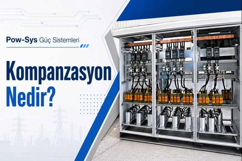
Power factor correction systems are critical systems that improve power factor by regulating the reactive power balance of the facility and help the electrical infrastructure operate more efficiently. Therefore, the tests and maintenance required for power factor correction systems are not performed only to answer whether the panel is operating. The main purpose is to verify that capacitor steps, switching elements, reactors, protection components and the measurement chain operate healthily together. Because a small fault in a power factor correction system can turn into reactive penalties, overheating, resonance, capacitor damage or internal panel faults over time.
The first step of maintenance is always safety. Before working on a power factor correction panel, the system should be safely taken out of service, the appropriate discharge time should be waited and it should be verified that no residual voltage remains at capacitor terminals. Because capacitors can retain voltage for a period after energy is disconnected. Therefore, maintenance of a power factor correction panel should not be considered an ordinary panel cover opening task; it should be handled with the logic of equipment that stores energy.
Visual inspection is the basis of maintenance. The panel body, doors, ventilation grilles, filters, busbars, cable entries, fuse holders, capacitor bodies, contactors and reactors should be visually inspected. Signs such as swelling, leakage, cracks, darkening, burn marks, rust, corrosion, looseness, deterioration in insulation material and insect or dust accumulation should be taken seriously. A large part of power factor correction faults gives its first signs during visual inspection.
Panel interior cleaning is one of the critical steps of power factor correction maintenance. Dust, moisture, metal particles and dirt accumulation can weaken insulation safety over time, disturb contactor movement and cause temperature rise. Especially in panels with fans and filters, a clogged air filter increases internal temperature and reduces capacitor life. Therefore, filters, ventilation paths and the panel interior should be cleaned regularly, and maintenance frequency should be increased in dirty environments.
The physical condition of capacitors requires special attention. If swelling, deformation, leakage, pressure relief mark, darkening around terminals or enclosure deterioration is present on the body, the related step should be evaluated in detail. Since capacitors are the main elements that produce reactive power, capacity loss or internal damage here directly disturbs power factor correction performance. Therefore, not only the presence of capacitors but whether they actually produce healthy capacity should also be monitored.
Capacitance reduction in capacitor steps can develop silently over time. Even if the system appears to be operating from the outside, the real kvar output of a specific step may have decreased. Therefore, during maintenance, step-based current measurements, capacitance checks when required and phase balance observations should be performed. Clear imbalance in phase currents or deviations incompatible with nominal values may show a problem in the related capacitor group.
Fuses and switches are also main components of power factor correction maintenance. Power circuit fuses, step protection elements, auxiliary circuit fuses and panel incoming protections should be checked both visually and functionally. A blown fuse does not always mean only a fuse problem; often there is a capacitor fault, contactor problem or harmonic stress behind it. Therefore, replacing the faulty fuse and moving on is not the correct maintenance approach.
Contactors are among the most frequently operating parts in power factor correction systems. Especially in automatic stepped systems, contactors may open and close many times during the day. Therefore, signs such as darkening on plastic parts, wear on contact surfaces, deterioration in auxiliary contacts, coil heating, mechanical sticking or abnormal sound should be monitored. In dirty environments, cleaning and, if necessary, replacement of contactors are important parts of the maintenance plan.
Reactors should be evaluated separately in detuned power factor correction systems used in facilities with harmonics. If excessive heating, varnish smell, discoloration, mechanical looseness, increased core noise or terminal darkening is seen on the reactor body, this is a sign of serious stress. Detuned systems are selected to reduce resonance risk; however, if the reactor itself is faulty, the system cannot provide the expected protection. Therefore, in facilities with harmonics, not only capacitor health but also reactor health should be continuously tracked.
The power factor relay or power factor correction controller is the brain of the system. The cos phi target, step sequence, delay settings, CT ratio and measurement accuracy of this device should be checked. If the relay is not set correctly, even healthy capacitor steps can switch in the wrong order and overcompensation or insufficient compensation may occur. Therefore, when investigating a power factor correction fault, not only the power circuit but also the control logic must be examined.
Current transformer connections directly affect power factor correction performance. If the CT ratio, direction, secondary connection and relay definition are not correct, the system perceives the real load condition incorrectly. As a result, steps do not switch in as required or unnecessary switching occurs. Therefore, CT polarity, secondary connection safety and compatibility with the relay should be verified separately in power factor correction maintenance.
Connection tightness is very important in power factor correction panels. Capacitor terminals, busbar connections, reactor ends, contactor outputs, cable lugs and grounding points should be checked for torque. Loose connections can cause increased contact resistance and serious hot spots over time. This shortens capacitor life and can create fire risk. Therefore, internal panel torque control is one of the main parts of maintenance.
Thermal camera inspection is a very efficient tool for power factor correction maintenance. When steps, fuses, contactor terminals, reactor ends, main busbar connections and panel incoming points are thermally inspected, looseness and overloading that cannot be noticed visually can be seen early. The important point here is to evaluate differences between similar phases and similar steps as much as absolute temperature.
Harmonic assessment is especially important in facilities where drives, UPSs, rectifiers and nonlinear loads are dense. Even if the power factor correction system is correct, the harmonic level may change over time and create unexpected stress on capacitors. If THD increases, resonance approaches, fuses frequently blow or recurring faults occur in steps, the harmonic compatibility of the power factor correction system should be reassessed.
At the end of maintenance, all results must be recorded. Which step is problematic, which fuse was replaced, which connection was found loose, reactor temperatures, thermal images, power factor relay settings and measured current values should be archived regularly. Because power factor correction problems usually do not appear suddenly; they grow over time. If trend tracking is performed, capacity loss, excessive switching and heating problems can be noticed before a fault occurs. In summary, the tests and maintenance required for power factor correction systems consist of visual inspection, panel cleaning, capacitor and contactor checks, fuse/switch verification, temperature and resonance awareness in detuned systems, controller and CT compatibility, connection torque, thermal inspection and harmonic assessment carried out together. If the power factor correction system, harmonic effects, panel modernization and general power quality in your facility will be evaluated together, LV/MV/HV project design and consultancy and HV/MV testing, maintenance and repair services for general field suitability can support the technical decision process.
Related Blog Posts
Related Services
Frequently Asked Questions
Why is maintenance required on power factor correction systems?
Maintenance is required because power factor correction systems regulate the reactive power balance of the facility, and the capacitors, contactors, fuses, reactors and relays they contain can wear or become stressed over time. The main purpose of maintenance is to verify that the capacitor steps, switching elements, reactors, protection components and measurement chain still operate healthily together, not just that the panel appears to run. A small fault in a power factor correction system can turn into reactive penalties, overheating, resonance, capacitor damage or internal panel faults over time. If regular maintenance is not performed, capacity loss, loose connections, contactor wear and harmonic stress can progress unnoticed, and reactive penalty, overheating and fault risk increase. Because these panels also contain equipment that stores energy, maintaining them protects power factor, panel safety and the reliability of the facility's electrical infrastructure.
Which checks are performed in a power factor correction panel?
Visual inspection, panel interior cleaning, capacitor body and terminal checks, fuse and switch inspection, contactor inspection, reactor temperature checks, controller settings, CT connection verification and thermal inspection can be performed. Visual inspection covers the panel body, busbars, fuse holders, capacitor bodies, contactors and reactors, looking for swelling, leakage, cracks, darkening, burn marks, rust and looseness. Cleaning removes dust, moisture and metal particles that weaken insulation and disturb contactor movement. Capacitor steps are checked for physical condition and, when required, capacitance and phase balance, while fuses and switches are verified both visually and functionally. The power factor relay settings, CT ratio, direction and polarity are confirmed, connection torque is checked, and reactors are assessed in detuned systems. Thermal inspection and harmonic assessment complete the work. The scope depends on whether the system is a standard or detuned design and on the facility's load.
Which signs indicate capacitor failure?
Swelling, deformation, leakage, a pressure relief mark, darkening around the terminals, enclosure deterioration, terminal heating, capacitance reduction and current imbalance between phases are among the most important signs of capacitor failure. Because capacitors are the main elements that produce reactive power, any capacity loss or internal damage directly disturbs power factor correction performance, so it is not enough to confirm that the capacitors are present; whether they actually produce healthy capacity should also be monitored. Capacitance reduction in a step can develop silently over time, and even if the system appears to be operating from the outside, the real kvar output of a specific step may have decreased. For this reason, step-based current measurements, capacitance checks when required and phase balance observations are used during maintenance. A clear imbalance in phase currents or deviations from nominal values may point to a problem in the related capacitor group.
Why do contactors require special checking?
Contactors require special checking because they are among the most frequently operating parts in power factor correction systems. In automatic stepped systems, contactors may open and close many times during the day, so they wear faster than most other components in the panel. For this reason, signs such as darkening on plastic parts, wear on contact surfaces, deterioration in auxiliary contacts, coil heating, mechanical sticking or abnormal sound should be monitored during maintenance. Contact wear, coil problems and mechanical sticking can prevent steps from switching in and out properly over time, which disturbs the compensation the system is meant to provide. In dirty environments, cleaning and, if necessary, replacement of contactors become important parts of the maintenance plan. Because a contactor that fails to operate keeps a healthy capacitor step out of service, the switching elements are checked as carefully as the capacitors themselves.
Why is extra attention required in detuned power factor correction?
Extra attention is required in detuned power factor correction because these systems use reactors to reduce resonance risk in facilities with harmonics, and the reactors themselves become a component that can fail. If excessive heating, a varnish smell, discoloration, mechanical looseness, increased core noise or terminal darkening is seen on the reactor body, this is a sign of serious stress. Detuned systems are selected precisely to lower resonance risk, but if the reactor itself is faulty, the system cannot provide the expected protection. For this reason, in facilities with harmonics, not only capacitor health but also reactor health should be continuously tracked. Reactor failure, overheating or incorrect operation can shorten capacitor life and cause protections to trip, so the reactors are evaluated separately as a distinct maintenance item. Following reactor temperature and condition together with the capacitor steps keeps the detuned system working as intended.
Why should the power factor relay be checked?
The power factor relay, or power factor correction controller, should be checked because it is the brain of the system. Its cos phi target, step sequence, delay settings, CT ratio and measurement accuracy all determine how the steps switch. If the relay is not set correctly, even healthy capacitor steps can switch in the wrong order, and overcompensation or insufficient compensation may occur. A relay that is incorrectly set or incompatible with the CT therefore undermines the whole system even when the power circuit is sound. For this reason, when investigating a power factor correction fault, not only the power circuit but also the control logic must be examined. Checking the relay settings and their compatibility with the current transformer ensures that the correct steps switch in at the right time, which is what actually delivers the intended power factor and avoids reactive penalties or unnecessary switching.
How does the CT connection affect power factor correction?
The CT connection directly affects power factor correction performance, because the controller relies on the current transformer to read the facility's real load. If the CT ratio, direction, polarity, secondary connection or relay definition is not correct, the system perceives the actual load condition incorrectly. As a result, steps do not switch in as required, or unnecessary switching occurs, and the intended power factor is not achieved even when the capacitors and contactors are healthy. For this reason, CT polarity, secondary connection safety and compatibility with the relay should be verified separately in power factor correction maintenance. Because an error in the measurement chain misleads the controller about how much reactive power is needed, a CT problem can look like a step or capacitor fault from the outside. Confirming the CT connection is therefore a basic step in diagnosing why a power factor correction panel is not compensating correctly.
What does a thermal camera show in power factor correction maintenance?
A thermal camera shows hot spots caused by loose connections or increased contact resistance at an early stage. When the steps, fuses, contactor terminals, reactor ends, main busbar connections and panel incoming points are thermally inspected, looseness and overloading that cannot be noticed visually can be seen before they cause a fault. The important point is to evaluate differences between similar phases and similar steps as much as the absolute temperature, because a relative difference is what reveals a developing problem. Connection tightness is very important in power factor correction panels, since loose capacitor terminals, busbar connections, reactor ends, contactor outputs, cable lugs and grounding points can raise contact resistance and create serious hot spots over time. Because such heating shortens capacitor life and can create fire risk, thermal inspection is a very efficient tool, and its findings are compared with previous images and similar steps as part of trend tracking.
Does harmonic increase affect the power factor correction system?
Yes, an increase in harmonics affects the power factor correction system. Harmonic assessment is especially important in facilities where drives, UPSs, rectifiers and other nonlinear loads are dense, because even if the power factor correction system is correct, the harmonic level may change over time and create unexpected stress on the capacitors. Harmonics can increase resonance risk, shorten capacitor life and cause protections to trip. If THD increases, resonance approaches, fuses frequently blow or recurring faults occur in the steps, the harmonic compatibility of the power factor correction system should be reassessed. For this reason the system should be evaluated regularly in facilities with harmonics, and reactor health should be tracked together with capacitor health in detuned designs. Because harmonic stress can turn a correctly sized system into a source of faults, following the harmonic environment is part of keeping the compensation reliable over time.
Why is record keeping important in power factor correction maintenance?
Record keeping is important because power factor correction problems usually do not appear suddenly; they grow over time. At the end of maintenance, which step is problematic, which fuse was replaced, which connection was found loose, reactor temperatures, thermal images, power factor relay settings and measured current values should all be archived regularly. When this data is kept, capacitance loss, temperature rise, fuse faults and step behavior can be compared from one visit to the next. If trend tracking is performed, capacity loss, excessive switching and heating problems can be noticed before a fault occurs. Because a blown fuse often has a capacitor fault, contactor problem or harmonic stress behind it, keeping a history helps connect repeated faults to their real cause rather than treating each one in isolation. In this way, records turn individual observations into a clear picture of how the panel and its steps are aging.