
Summary Highlights
- What relay setting calculations are: the engineering study that determines at which current, in what time and under which condition a protection relay will trip
- What relay setting calculations do: detect the fault quickly, keep the healthy section energized and ensure equipment safety
- How relay setting calculations are performed: determining pickup and time settings with load current, short-circuit current, CT/VT ratio, equipment withstand and coordination data
- Main subjects examined: pickup/start current, inverse-definite time curves, instantaneous trip, earth fault, directional protection and selectivity margin
- Application areas: protection coordination in MV/HV switchgear, transformer protection, feeder protection, motor feeders, generators and distribution systems
Article Details
Relay setting calculations are an engineering study that determines what magnitude of current a protection relay will identify as a fault, how long it will take to trip and under which condition it will be blocked or behave directionally. In short, the answer to the question of what relay setting calculations are: they are the calculation process that defines what the protection system will trip, when it will trip and in what order. This study is not only entering numbers into a relay menu; it means understanding system behavior and building the settings accordingly.
Selectivity is at the center of the question of what relay setting calculations do. When a fault occurs, the ideal result is that only the faulty section is disconnected and the healthy sections remain energized. If relay settings are not made correctly, either tripping occurs too late and equipment is damaged, or upstream circuit breakers trip unnecessarily and a wider area loses power. Therefore, relay setting is a critical subject in terms of both safety and operational continuity.
The answer to why relay setting calculations are necessary is not only to make the relay operate. Relay setting is necessary to protect the cable, transformer, motor, busbar, circuit breaker and human safety. An incorrect pickup value may interpret normal load as a fault. An incorrect time curve may disrupt coordination with the downstream device. If the instantaneous stage is selected too low, unwanted tripping may occur during starting or energization current. For this reason, setting calculation is the foundation of protection engineering.
The first answer to how relay setting calculations are performed is data collection. Correct settings cannot be calculated without knowing utility short-circuit power, transformer rating and impedance, cable length and cross-section, motor powers, existing circuit breaker and relay types, CT/VT ratios, load currents and equipment withstand values. In other words, the system model is first created, and then the protection philosophy is established according to this model. The numbers entered into the relay menu are the result of this technical picture.
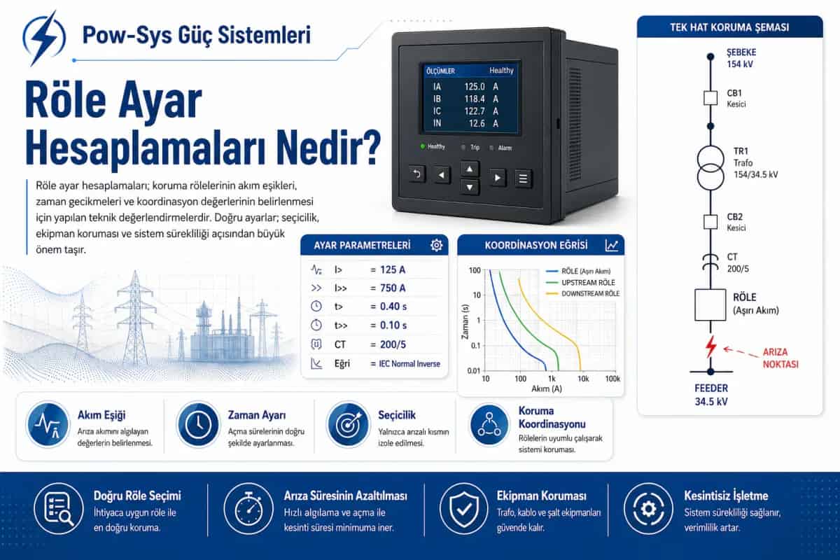
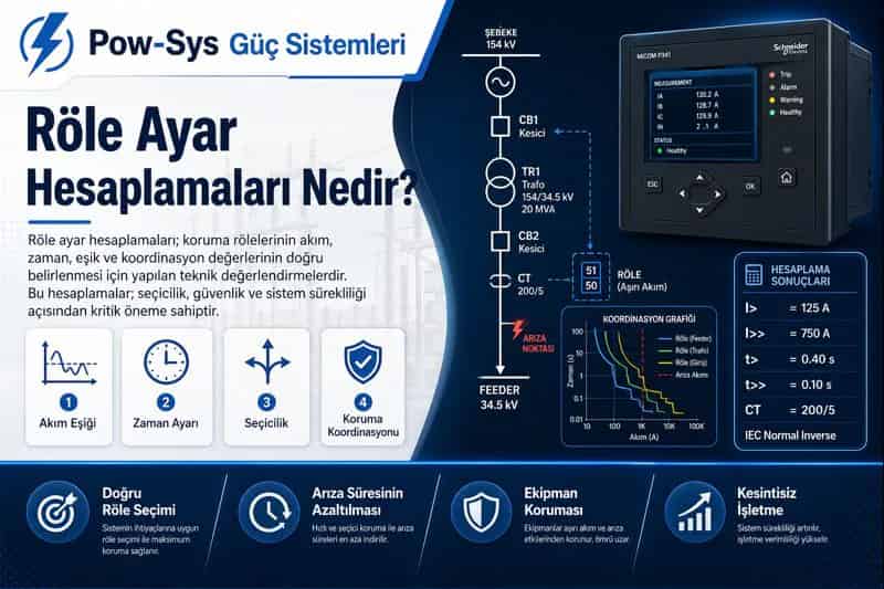
The most basic concept in setting calculation is the pickup or start current value. This setting determines from which current level the relay will begin to see overcurrent or earth fault. If pickup is selected too low, normal load increases, motor starting or transient events may operate the relay unnecessarily. If it is selected too high, the relay may not see the fault with sufficient sensitivity. Therefore, pickup setting is generally selected above the maximum load current, but at a level that can also reliably see the minimum fault current in the protected section.
The time curve and time dial or TMS setting are also among the main subjects of relay calculations. Curves such as inverse, very inverse, extremely inverse or definite time determine how quickly the relay will trip as the fault current increases. Time dial or TMS shifts this curve on the time axis. Two relays with the same pickup value may trip in different times when different time dial values are selected. Therefore, in coordination calculation, not only the current level but also the curve and time step are considered together.
The instantaneous trip stage requires separate attention. This stage is used to provide an instantaneous or very short-time trip above a certain short-circuit current level. The aim is to clear nearby severe faults very quickly. However, if the instantaneous level is selected too low, selectivity may be lost during transformer energizing current, motor starting current or downstream faults. Therefore, when setting the instantaneous stage, both the minimum close-in fault current and unwanted transient currents should be considered together.
Earth fault relay settings are evaluated with a different logic than phase overcurrent settings. Because the current level seen in earth faults may vary greatly depending on the system grounding method. Earth fault currents seen in resistance-grounded, impedance-grounded or solidly grounded systems are not the same. Therefore, when setting functions such as Io>, 51N, 50N and 51G, both the system grounding structure and the minimum earth fault current must be known. Earth fault setting should be established with a balance between sensitivity and the risk of nuisance tripping.
In systems with directional protection, relay setting calculations become one step more complex. Especially in ring networks, parallel supplies and structures with bidirectional power flow, the relay must evaluate not only the magnitude of the current but also the direction in which the current flows. At this point, a voltage signal or suitable direction-determination logic is used for polarization. In other words, when setting directional overcurrent, correct directional logic must be established in addition to pickup and time calculation.
The CT ratio plays a critical role in relay setting calculations. The relay does not see the primary system directly; it usually sees it through CTs and VTs. Therefore, an incorrect CT ratio, incorrect polarity or incorrect secondary connection can practically invalidate the entire setting calculation. Even if the pickup value appears correct on paper, if the CT transformation is wrong, the relay will not operate at the expected point in the field. For this reason, the setting calculation and the accuracy of the measuring chain should be evaluated together.
When relay settings are made, not only fault current but also normal operating currents should be considered. Motor starting, transformer inrush current, cold load pickup, temporary loading and some special process currents are natural events that may cause the relay to operate incorrectly. A good relay setting must be able to tolerate these normal or temporary conditions without missing the fault. Therefore, relay setting requires operational knowledge as much as protection knowledge.
Coordination margin is also one of the important parts of the setting calculation. If a certain time difference is not left between the downstream relay and the upstream relay, both devices may trip for the same fault. This is an unwanted situation. Therefore, time-current curves are drawn, fault levels are examined at different points and enough margin is left for the downstream stage to trip first. The subject we call relay coordination is largely the result of this setting calculation.
Relay setting calculations are not a static study. Adding a new transformer to the system, connecting a generator, increasing motor capacity, increasing the utility short-circuit level or changing the cable arrangement may invalidate the existing settings. Therefore, settings are not made once and forgotten. As the facility changes, the protection study must also be updated. Old settings may create risk for the new system.
This study is often carried out together with short-circuit analysis and protection coordination study. First, possible fault currents in the system are found; then pickup and time stages are calculated according to these fault current levels. Then the curves are placed over one another and it is checked which relay will trip first and which will trip later. In other words, relay setting calculations are not a standalone item; they are an engineering process placed inside system analysis.
In summary, relay setting calculations are a fundamental engineering study that determines at which current, in what time and with what logic a protection relay will trip. Pickup, time curve, TMS, instantaneous trip, earth fault, directional protection and coordination margin are the main components of this study. A correctly made relay setting does not only clear the fault; it protects the healthy section, supports equipment life and improves system safety. If short-circuit analysis, relay coordination, MV/HV protection system and field suitability will be evaluated together in your facility, LV/MV/HV project design and consultancy and HV/MV testing, maintenance and repair works can technically support this process.
Related Blog Posts
- What Tests and Maintenance Are Required for Distance Protection Relays?
- What Tests and Maintenance Are Required for Transformer Differential Protection Relays?
- What Tests and Maintenance Are Required for Overcurrent and Earth Fault Protection Relays?
- What Tests and Maintenance Are Required for Breaker Failure and Busbar Protection Relays?
Related Services
Frequently Asked Questions
What are relay setting calculations?
Relay setting calculations are an engineering study that determines what magnitude of current a protection relay will identify as a fault, how long it will take to trip and under which condition it will be blocked or behave directionally. In short, they are the calculation process that defines what the protection system will trip, when it will trip and in what order. This study is not only entering numbers into a relay menu; it means understanding system behavior and building the settings accordingly. The system model is first created from data such as short-circuit currents, load currents and CT/VT ratios, and the protection philosophy is then established according to this model. Pickup, time curve, TMS, instantaneous trip, earth fault, directional protection and coordination margin are the main components of the study, and the numbers entered into the relay menu are the result of this technical picture.
Why are relay setting calculations necessary?
Relay setting calculations are necessary to isolate the faulty section quickly and selectively, keep the healthy section energized, protect equipment and prevent nuisance trips. Their purpose is not only to make the relay operate: correct settings protect the cable, transformer, motor, busbar, circuit breaker and human safety. When a fault occurs, the ideal result is that only the faulty section is disconnected and the healthy sections remain energized. If relay settings are not made correctly, either tripping occurs too late and equipment is damaged, or upstream circuit breakers trip unnecessarily and a wider area loses power. An incorrect pickup value may interpret normal load as a fault, an incorrect time curve may disrupt coordination with the downstream device, and an instantaneous stage selected too low may trip during starting or energization current. For this reason, setting calculation is the foundation of protection engineering.
What does pickup setting mean?
Pickup or start current is the threshold value at which the relay begins to see overcurrent or earth fault, and it is the basic setting that determines the sensitivity of the relay. If pickup is selected too low, normal load increases, motor starting or transient events may operate the relay unnecessarily. If it is selected too high, the relay may not see the fault with sufficient sensitivity. Therefore, pickup is generally selected above the maximum load current, but at a level that can also reliably see the minimum fault current in the protected section. The CT ratio plays a critical role here, because the relay usually sees the primary system through CTs and VTs: even if the pickup value appears correct on paper, an incorrect CT ratio, polarity or secondary connection means the relay will not operate at the expected point in the field.
What does time dial or TMS mean?
Time dial or TMS is the setting that shifts the selected time-current curve on the time axis, changing how quickly the relay trips. Curves such as inverse, very inverse, extremely inverse or definite time determine how fast the relay will trip as the fault current increases, and the time dial positions this curve so the same characteristic can operate faster or slower. Two relays with the same pickup value may trip in different times when different time dial values are selected. Therefore, in coordination calculation, not only the current level but also the curve type and time step are considered together. Time-current curves are drawn and placed over one another, fault levels are examined at different points and enough margin is left for the downstream stage to trip first. In this way, both fast fault clearing and selectivity are achieved at the same time.
How should the instantaneous trip setting be considered?
The instantaneous stage is used to provide a trip without delay, or with a very short delay, above a certain short-circuit current level. Its aim is to clear nearby severe faults very quickly, which is why it requires separate attention during setting calculations. However, if the instantaneous level is selected too low, selectivity may be lost during transformer energizing current, motor starting current or downstream faults, and nuisance tripping may occur. Therefore, when setting the instantaneous stage, both the minimum close-in fault current and unwanted transient currents should be considered together. Normal operating events such as motor starting, transformer inrush current, cold load pickup and temporary loading are natural situations that may cause the relay to operate incorrectly. A good relay setting must be able to tolerate these normal or temporary conditions without missing a real fault.
Why is the earth fault relay setting different?
The earth fault relay setting is different because the current level seen in earth faults may vary greatly depending on the system grounding method. Earth fault currents seen in resistance-grounded, impedance-grounded or solidly grounded systems are not the same. Therefore, when setting functions such as Io>, 51N, 50N and 51G, both the system grounding structure and the minimum earth fault current must be known. This is why earth fault settings are evaluated with a different logic than phase overcurrent settings and cannot simply copy the phase protection approach. The earth fault setting should be established with a balance between sensitivity and the risk of nuisance tripping: it must be sensitive enough to see the minimum earth fault current in the protected section, yet secure enough not to operate for transient conditions that are not real faults.
When is directional relay setting required?
Directional relay setting is required in ring networks, parallel supplies and structures with bidirectional power flow. In these systems, the relay must evaluate not only the magnitude of the current but also the direction in which the current flows; otherwise it cannot act selectively for faults fed from different sides. For polarization, a voltage signal or a suitable direction-determination logic is used. This means that when setting directional overcurrent protection, correct directional logic must be established in addition to the pickup and time calculation, so relay setting calculations become one step more complex in systems with directional protection. If the direction logic is not built correctly, a setting based only on current magnitude cannot provide selectivity in a network with bidirectional power flow. Directional behavior is therefore treated as an integral part of the setting study, not as an optional extra.
Which data do relay setting calculations depend on?
Relay setting calculations depend on utility short-circuit power and short-circuit currents, load currents, CT/VT ratios, equipment withstand values, transformer rating and impedance, cable length and cross-section, motor powers and starting currents, transformer inrush effect, existing circuit breaker and relay types, and upstream-downstream protection coordination data. Correct settings cannot be calculated without knowing this information: the system model is first created, and the protection philosophy is then established according to this model. The study is often carried out together with short-circuit analysis and a protection coordination study. First, possible fault currents in the system are found; then pickup and time stages are calculated according to these fault current levels; finally, the curves are compared to check which relay will trip first. The numbers entered into the relay menu are the result of this technical picture, so missing data undermines the whole calculation.
Are relay setting and protection coordination the same thing?
They are not exactly the same, but they are directly connected, because relay setting calculations form the main input of the protection coordination study. Coordination margin is one of the important parts of the setting calculation: if a certain time difference is not left between the downstream relay and the upstream relay, both devices may trip for the same fault, which is an unwanted situation. Therefore, time-current curves are drawn, fault levels are examined at different points and enough margin is left for the downstream stage to trip first. The process usually runs together with short-circuit analysis: possible fault currents are found, pickup and time stages are calculated according to these levels, and the curves are then placed over one another to check which relay will trip first and which later. Relay coordination is therefore largely the result of a correctly performed setting calculation.
Should relay settings be updated if the system changes?
Yes, relay settings should be reviewed when the system changes, because relay setting calculations are not a static study. Adding a new transformer, connecting a generator, increasing motor capacity, increasing the utility short-circuit level or changing the cable arrangement may invalidate the existing settings. Such changes directly affect the short-circuit levels and the upstream-downstream coordination on which the original calculation was based. Therefore, settings are not made once and forgotten; as the facility changes, the protection study must also be updated. Old settings may create risk for the new system, because the relay may then trip too late during a real fault or may see normal operation as a fault and cause unnecessary outages. The correct approach is to renew the short-circuit analysis and the protection coordination study together after every significant system change and to update the relay settings accordingly.