

Summary Highlights
- What power factor correction is: an electrical correction method that improves power factor by balancing reactive power
- What power factor correction does: reducing unnecessary reactive current, lowering losses and using system capacity more efficiently
- How power factor correction works: balancing reactive power drawn by inductive loads with capacitor banks or suitable solutions
- Power factor correction types: fixed, stepped automatic, local, group, central and detuned reactor solutions according to harmonic effects
- Selection and use: load structure, harmonic level, power factor target, panel structure and protection elements
Article Details
Power factor correction is the electrical adjustment process performed in electrical installations to balance reactive power and improve the power factor. In short, the answer to what power factor correction is: it is a correction method that enables the system to operate more efficiently by reducing the reactive power drawn from the grid by inductive loads. Therefore, power factor correction is not only a panel or a few capacitors; it is an engineering application directly related to the facility's power quality and energy use.
At the center of what power factor correction does is the power factor. In industrial facilities, commercial buildings and operations with large electrical loads, motors, transformers, ballasts and similar inductive loads create a phase difference between current and voltage. This causes reactive power to be drawn in addition to active power. Reactive power does not directly turn into useful work, but it increases current circulation in the transmission and distribution system. The purpose of power factor correction is to reduce this unnecessary reactive current requirement as much as possible.
It would be incomplete to answer why power factor correction is necessary only by saying that it reduces the risk of reactive penalties. A well-designed correction system improves the power factor and reduces the total current requirement. When current decreases, the load on cables, busbars and transformers decreases; voltage drop and losses can be limited; the facility's existing capacity can be used more efficiently. In other words, power factor correction is not only a billing topic but also a technical efficiency topic.
The basic answer to how power factor correction works is this: a capacitive reactive power source is added to the system to balance the lagging reactive power drawn by inductive loads. In most applications, this is done with capacitor banks. Capacitors provide leading reactive power and balance the effect of inductive loads. As a result, the total reactive current that the grid must carry decreases and the power factor moves closer to unity.
It is difficult to evaluate power factor correction correctly without understanding the concept of power factor. Power factor is one of the basic indicators showing how efficiently a system operates. As the value approaches unity, the unnecessary reactive component carried for the active power decreases. Low power factor means that more current is drawn to perform the same work and system elements are stressed more. For this reason, compensation is also defined as a power factor correction application.
Power factor correction systems are not installed in the same way in every facility. The simplest application is fixed correction. In this method, a capacitor that remains permanently connected is used for a specific load or section. It may work in systems where the load characteristic does not change much. However, more flexible solutions are required in facilities with high load fluctuation. At this point, automatic step-controlled power factor correction panels come to the fore.
In automatic correction systems, the power factor relay or APFC relay monitors the facility's instantaneous reactive power need and switches capacitor steps in and out according to the requirement. Thus, the system shows dynamic behavior that adapts to load changes instead of a fixed solution. When load increases or decreases, the appropriate number of steps is selected and the risk of over- or under-compensation is reduced. Therefore, automatic correction is a much more suitable approach for operations with variable load profiles.
Power factor correction applications may also differ in terms of placement. Local correction means connecting the capacitor near the load that produces reactive power. In group correction, similar load groups are handled together. In central correction, general correction is performed at the main distribution panel or the main point of the facility. Which method is more correct is determined according to the facility's load distribution, cable lengths, process structure and maintenance approach.
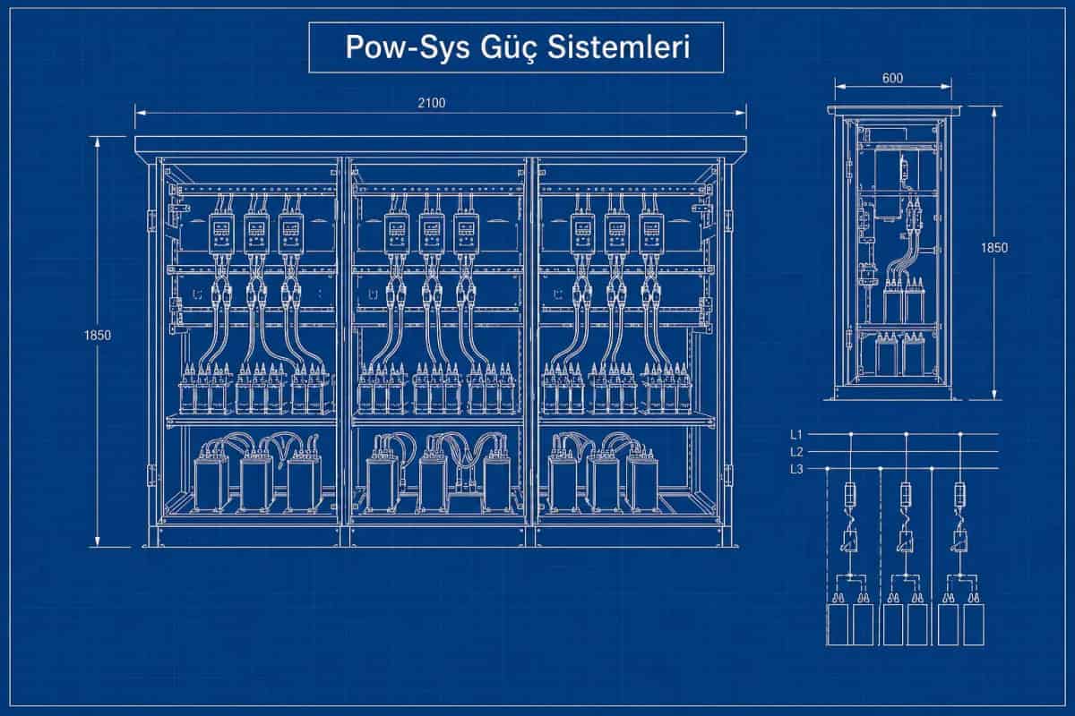
When a power factor correction system is mentioned, only capacitors should not come to mind. In practice, a correction panel includes capacitor steps, contactors or switching elements, fuses or breakers, a power factor relay, current transformer connection, protection elements and discharge resistors in many applications. In systems with harmonics, series reactors may also be added. In other words, a correction panel is a structure in which multiple elements work together so that reactive power generation can be performed safely and controllably.
Harmonics are a very critical topic in power factor correction. If the facility contains drives, rectifiers, UPS systems, welding machines or similar nonlinear loads, an ordinary capacitor bank may not always be the correct solution. In such systems, resonance, overheating and capacitor stress risks may occur. Therefore, detuned reactor correction or filtered solutions may be required depending on the harmonic level. Harmonic analysis should not be ignored when preparing a correction project.
Power factor correction and harmonic filtering are not the same thing, but in some facilities these two topics must be considered together. Power factor correction mainly focuses on reactive power balance. Harmonic filtering aims to reduce current and voltage distortion. Still, if the correction system is not designed correctly in facilities with harmonics, the problem may grow. Therefore, especially in industrial structures, load characteristics must be analyzed when selecting a correction system.
Another benefit of power factor correction is that it helps use existing transformer and cable capacity more efficiently. When reactive current decreases, active power can be carried more healthily through the same infrastructure. In some facilities, this may delay the need for new transformer or cable investment. Of course, every situation must be evaluated separately, but the positive effect of well-designed correction on system capacity is often clear.
Incorrect power factor correction can also create risk. Over-compensation, overly large step selection, incorrect current transformer connection, wrong relay setting or capacitor banks selected without considering harmonics may cause system problems. Therefore, correction is not only installing a panel; it requires correct engineering calculation, correct step structure and correct field application.
In summary, power factor correction is a basic electrical engineering application that improves the power factor by balancing reactive power in electrical installations, reduces unnecessary current carried by the grid and helps the system operate more efficiently. It can be applied as fixed, automatic, local, group or central correction; in facilities with harmonics, reactor or filter-based approaches may be required. If power factor correction need, power factor analysis, panel selection and harmonic effects need to be evaluated together in your facility, LV/MV/HV project design and consultancy, HV/MV testing, maintenance and repair for general field suitability and related technical studies for holistic assessment of the energy infrastructure can be planned together.
Related Blog Posts
Related Services
Frequently Asked Questions
What is power factor correction?
Power factor correction is the electrical adjustment process performed in electrical installations to balance reactive power and improve the power factor. It is a correction method that enables the system to operate more efficiently by reducing the reactive power drawn from the grid by inductive loads such as motors, transformers and ballasts. These inductive loads create a phase difference between current and voltage, which causes reactive power to be drawn in addition to active power; reactive power does not directly turn into useful work, but it increases current circulation in the transmission and distribution system. Power factor correction, also called reactive power compensation, reduces this unnecessary reactive current requirement as much as possible. It is therefore not only a panel or a few capacitors: it is an engineering application directly related to the facility's power quality and energy use.
What does power factor correction do?
Power factor correction reduces unnecessary reactive current, helps correct the power factor and allows system elements to be used more efficiently. In industrial facilities, commercial buildings and operations with large electrical loads, motors, transformers, ballasts and similar inductive loads draw reactive power in addition to active power, and this increases current circulation in the transmission and distribution system. A well-designed correction system improves the power factor and reduces the total current requirement: when current decreases, the load on cables, busbars and transformers decreases, voltage drop and losses can be limited, and the facility's existing capacity can be used more efficiently. Answering only with the reduction of reactive penalty risk would be incomplete, because power factor correction is not only a billing topic but also a technical efficiency topic that affects the whole installation.
How does power factor correction work?
Power factor correction works by adding a capacitive reactive power source to the system to balance the lagging reactive power drawn by inductive loads. In most applications this is done with capacitor banks: capacitors provide leading reactive power and balance the effect of inductive loads, so the total reactive current that the grid must carry decreases and the power factor moves closer to unity. In automatic systems, a power factor relay, also called an APFC relay, monitors the facility's instantaneous reactive power need and switches capacitor steps in and out according to the requirement, adapting dynamically to load changes. A complete correction panel is more than capacitors alone: it includes capacitor steps, contactors or switching elements, fuses or breakers, the power factor relay, a current transformer connection, protection elements and, in many applications, discharge resistors.
Why is power factor correction necessary?
A low power factor means that more current is drawn to perform the same work and system elements are stressed more. Power factor correction is necessary because it reduces these effects: when the unnecessary reactive current decreases, the load on cables, busbars and transformers decreases, voltage drop and losses can be limited, and the facility's existing capacity can be used more efficiently. Answering only by pointing to the risk of reactive penalties would be incomplete, since correction is a technical efficiency topic as much as a billing one. Another practical benefit is capacity: when reactive current decreases, active power can be carried more healthily through the same infrastructure, and in some facilities this may delay the need for new transformer or cable investment. Power factor is one of the basic indicators of how efficiently a system operates, and correction keeps it close to unity.
What is automatic power factor correction?
Automatic power factor correction is a system that switches capacitor steps in and out automatically according to load changes and tries to keep the power factor stable. In these systems, the power factor relay or APFC relay monitors the facility's instantaneous reactive power need and selects the appropriate number of capacitor steps as the requirement changes. The system therefore shows dynamic behavior that adapts to load changes instead of providing a fixed solution: when the load increases or decreases, steps are added or removed and the risk of over- or under-compensation is reduced. This makes automatic step-controlled correction panels a much more suitable approach for operations with variable load profiles, whereas simple fixed correction, in which a capacitor remains permanently connected to a specific load or section, may only work where the load characteristic does not change much.
What are the types of power factor correction?
The main application types are fixed correction, automatic stepped correction, local correction, group correction and central correction. Fixed correction uses a capacitor that remains permanently connected for a specific load or section and may work where the load characteristic does not change much. Automatic step-controlled panels use a power factor relay to switch capacitor steps according to the instantaneous reactive power need, suiting facilities with high load fluctuation. In terms of placement, local correction connects the capacitor near the load that produces reactive power, group correction handles similar load groups together, and central correction is performed at the main distribution panel or the main point of the facility. In systems with harmonics, detuned reactor correction or filtered solutions may also be required. The right combination depends on load distribution, cable lengths, process structure and maintenance approach.
Why are capacitors used in power factor correction?
Capacitors are used because they provide leading, capacitive reactive power that balances the lagging reactive power drawn by inductive loads such as motors, transformers and ballasts. When capacitor banks supply this capacitive reactive power, the total reactive current that the grid must carry decreases and the power factor moves closer to unity. In most applications, capacitor banks are therefore the core of the correction system. However, a correction installation is never only capacitors: the panel also includes contactors or switching elements, fuses or breakers, a power factor relay, a current transformer connection, protection elements and, in many applications, discharge resistors. In facilities with harmonics, series reactors may be added, because ordinary capacitor banks may face resonance, overheating and capacitor stress risks when nonlinear loads such as drives, rectifiers, UPS systems or welding machines are present.
Is standard power factor correction sufficient in facilities with harmonics?
Not always. If the facility contains drives, rectifiers, UPS systems, welding machines or similar nonlinear loads, an ordinary capacitor bank may not be the correct solution, because resonance, overheating and capacitor stress risks may occur in such systems. Depending on the harmonic level, detuned reactor correction or filtered solutions may be required instead of standard capacitor banks, which is why harmonic analysis should not be ignored when preparing a correction project. It is also worth remembering that power factor correction and harmonic filtering are not the same thing: correction focuses on reactive power balance, while harmonic filtering aims to reduce current and voltage distortion. Still, in facilities with harmonics the two topics must be considered together, because a correction system that is not designed correctly in such an environment may make the existing problem grow rather than solve it.
Does power factor correction affect transformer capacity?
Yes, in a positive way when it is designed well. One of the benefits of power factor correction is that it helps use existing transformer and cable capacity more efficiently. When the reactive current decreases, active power can be carried more healthily through the same infrastructure, because the transformer and cables no longer have to carry the unnecessary reactive component alongside the useful power. In some facilities this may even delay the need for new transformer or cable investment. The same logic applies across the installation: as total current decreases, the load on cables, busbars and transformers decreases, and voltage drop and losses can be limited. Every situation must be evaluated separately, but the positive effect of well-designed correction on system capacity is often clear, which is why correction is treated as a technical efficiency measure and not only a billing measure.
Can incorrect power factor correction create problems?
Yes, incorrect correction can create real risks. Over-compensation, overly large step selection, incorrect current transformer connection, wrong relay settings or capacitor banks selected without considering harmonics may all cause system problems. In facilities with nonlinear loads such as drives, rectifiers, UPS systems and welding machines, an ordinary capacitor bank can lead to resonance, overheating and capacitor stress if the harmonic level is ignored, which is why detuned reactor or filtered solutions may be required. Automatic step control also matters here, because a properly configured power factor relay selects the appropriate number of steps as load changes and reduces the risk of over- or under-compensation. The practical conclusion is that correction is not only installing a panel: it requires correct engineering calculation, a correct step structure and correct field application to deliver its benefits safely.
What is the difference between power factor correction and harmonic filtering?
Power factor correction and harmonic filtering are not the same thing, although in some facilities they must be considered together. Power factor correction mainly focuses on reactive power balance: it reduces the lagging reactive power drawn by inductive loads, usually with capacitor banks, so the power factor moves closer to unity and the total current carried by the grid decreases. Harmonic filtering, on the other hand, aims to reduce current and voltage distortion created by nonlinear loads such as drives, rectifiers, UPS systems and welding machines. The connection between the two appears in facilities with harmonics: if the correction system is not designed correctly in such an environment, the problem may grow, with risks of resonance, overheating and capacitor stress. That is why load characteristics must be analyzed when selecting a correction system, especially in industrial structures.