Summary Highlights
- What a line trap is: its basic definition as a line trap or wave trap and its place in transmission systems
- What a line trap does: keeping the PLC/PLCC communication signal in the desired line section and reducing signal loss
- Line trap operating principle: low impedance at power frequency and high impedance at carrier frequency
- Equipment working with the line trap: relationship with coupling capacitor, CCVT/CVT, line tuner and PLC terminal
- Application areas and selection: correct approach for transmission lines, transformer substation terminals, communication and protection command transmission
Article Details
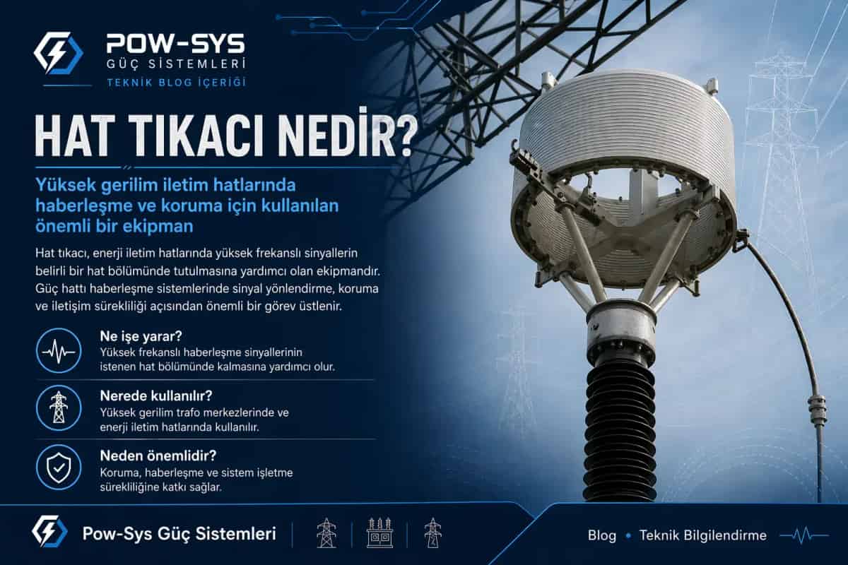
A line trap is special equipment used on high-voltage transmission lines to support healthy operation of power line carrier communication, or PLC/PLCC, systems. It is also called a wave trap. In short, the answer to what a line trap is: it is series-connected reactor-type equipment that keeps the communication frequency in the desired section of the power transmission line and helps the carrier signal propagate along the line in a controlled way. For related context, see What Tests and Maintenance Are Required for High-Voltage Lines?.
The core of what a line trap does is directing the communication signal. High-voltage lines can carry not only energy but also protection commands, teleprotection signals, certain data transmissions and voice communication. If these high-frequency carrier signals are not controlled, they may spread to the busbar side, neighboring lines or unwanted grid sections. The line trap helps keep these signals in the proper line section, increasing communication efficiency and reducing signal loss. For related context, see What Tests and Maintenance Are Required for Line Traps?.
The operating principle of a line trap is based on two different frequency behaviors. While the power system operates at the fundamental frequency of 50 or 60 Hz, PLC communication is carried out in a much higher frequency band. The line trap shows very low impedance to the power frequency, so it does not create a meaningful obstacle to energy transmission. In contrast, it shows high impedance to the carrier communication frequency and limits the flow of the high-frequency signal in an unwanted direction. In other words, it allows energy to pass while acting like a frequency-selective barrier for the communication signal. For related context, see What Is an MV XLPE Cable? What Does It Do, How Does It Work and What Structure Does It Have?.
For this reason, a line trap is not a protection relay, circuit breaker or disconnector. It is communication auxiliary equipment. Its basic duty in the system is not to interrupt current or isolate the circuit, but to control circulation of the high-frequency carrier signal. In this respect, it differs from switching equipment. However, its field effect should not be underestimated, because especially in teleprotection applications, keeping the signal on the correct line and at the correct terminal can directly affect protection performance. For related context, see What Is an MV Cable Termination? What Does It Do, How Does It Work and What Types Are There?.
A line trap is often mentioned together with a coupling capacitor or CCVT/CVT. This is because in power line carrier systems, the communication equipment is not connected directly to the high-voltage line but to the line through a suitable coupling arrangement. While the line trap helps keep the signal in the desired section on the series side, the coupling capacitor and line tuner side allow the PLC terminal to connect to the line in a controlled way. Therefore, the line trap should not be considered alone but as part of a line communication chain.
In transformer substations, the line trap is generally seen on the terminal side of the transmission line, near the line feeder. The application logic is to make it easier for the carrier signal to travel along the line toward the opposite substation and to limit leakage toward the busbar or other line sections. Therefore, the line trap location, line arrangement and position of coupling equipment must be handled together. A structure that is incorrectly located or incorrectly tuned may negatively affect communication performance.
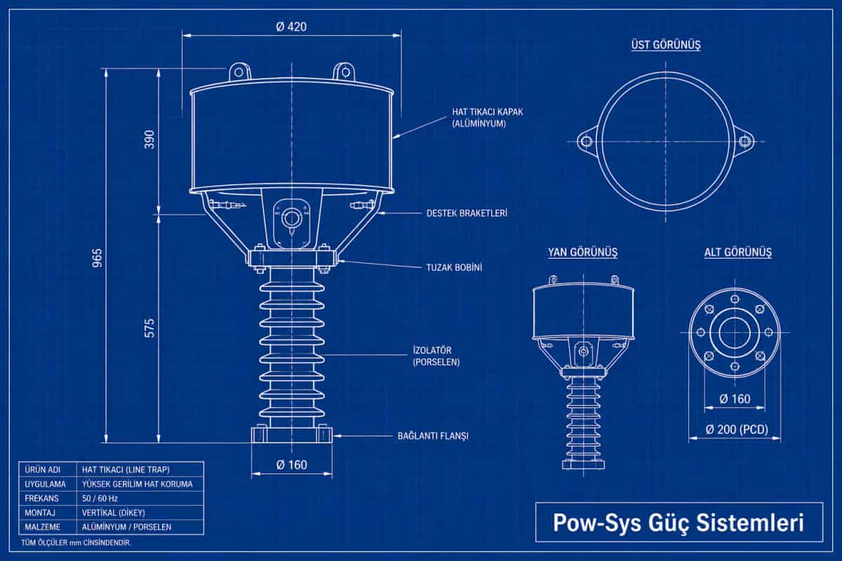
Structurally, a line trap has a design logic consisting of a main inductive coil and associated tuning elements. The main coil is designed to carry the full current of the transmission line. Therefore, the line trap is not physically light equipment. Since the power current passing through it is the actual line current, mechanical strength, short-circuit withstand and thermal behavior are important engineering topics for this equipment.
The concepts of line trap and reactor may sometimes be confused. Although both include inductive structures, their duties are different. System equipment such as shunt reactors or series reactors is used more for purposes such as voltage control, short-circuit current limitation or reactive power management. A line trap specifically aims to direct the carrier communication signal on a frequency basis. Therefore, even if they look similar, they should be evaluated in different functional classes.
In systems using line traps, PLC/PLCC communication is often related to line protection commands. For example, teleprotection, blocking, permissive or similar protection signals can be carried between the two ends of a transmission line. In some applications, voice and data communication are also carried out through the same approach. Therefore, the line trap is indirectly connected not only with communication quality but also with system protection reliability.
When selecting a line trap, the communication frequency alone is not considered. Line current, short-time thermal withstand, mechanical strength, impedance characteristic, tuning range, mounting arrangement and outdoor field conditions must be evaluated together. This equipment both carries full line current like a part of the power transmission system and behaves frequency-selectively like a part of the communication system. This dual character makes the design and selection process special.
In a substation with a line trap, the coupling capacitor, tuning device, connection conductors, grounding arrangement and PLC terminal chain must be considered together. Even a well-selected line trap may fail to provide the expected communication performance if it is not compatible with other coupling equipment. Therefore, the line trap should be handled not as a single device selection but as part of the coordinated design of the entire PLCC infrastructure.
In summary, a line trap is special transmission line equipment that keeps the carrier communication signal under control on a high-voltage line, allowing passage at power frequency while creating a selective barrier for the high-frequency communication component. It is one of the important auxiliary elements that enable energy transmission and communication infrastructure to operate together on the same line. If PLC/PLCC infrastructure, high-voltage line feeders, coupling equipment and MV/HV field layout need to be evaluated together in your facility, it is possible to proceed in an integrated way with HV/MV testing, maintenance and repair, LV/MV/HV project design and consultancy and HV operation responsibility services.
Related Blog Posts
- What Tests and Maintenance Are Required for High-Voltage Lines?
- What Tests and Maintenance Are Required for Line Traps?
- What Is an MV XLPE Cable? What Does It Do, How Does It Work and What Structure Does It Have?
- What Is an MV Cable Termination? What Does It Do, How Does It Work and What Types Are There?
Related Services
Frequently Asked Questions
What is a line trap?
A line trap, also called a wave trap, is special series-connected equipment used on high-voltage transmission lines to support healthy operation of power line carrier communication, known as PLC or PLCC. It is reactor-type equipment that keeps the communication frequency in the desired section of the power transmission line and helps the carrier signal propagate along the line in a controlled way. It is not a protection relay, circuit breaker or disconnector: its duty is not to interrupt current or isolate the circuit, but to control the circulation of the high-frequency carrier signal while the line continues to carry energy. Because it is connected in series with the line, it carries the full line current, which is why mechanical strength, short-circuit withstand and thermal behavior are important parts of its design.
What does a line trap do?
A line trap directs the communication signal so that it stays in the proper section of the high-voltage line. Transmission lines can carry not only energy but also protection commands, teleprotection signals, certain data transmissions and voice communication over PLC/PLCC systems. If these high-frequency carrier signals are not controlled, they may spread to the busbar side, neighboring lines or unwanted grid sections, weakening the communication link. The line trap reduces this leakage, keeps the signal traveling along the line toward the opposite substation, lowers signal loss and increases communication efficiency. Because teleprotection commands are often carried over the same channel, keeping the signal on the correct line and at the correct terminal can directly affect protection performance, which makes the line trap more important than a simple communication accessory.
How does a line trap work?
A line trap works by behaving differently at two frequency ranges. The power system operates at the fundamental frequency of 50 or 60 Hz, while PLC communication is carried out in a much higher frequency band. To the power frequency, the line trap shows very low impedance, so it creates no meaningful obstacle to energy transmission and the line current flows through it normally. To the carrier communication frequency, however, it shows high impedance and limits the flow of the high-frequency signal in unwanted directions. In other words, it allows energy to pass while acting like a frequency-selective barrier for the communication signal. Structurally, this behavior comes from a main inductive coil designed to carry full line current, combined with associated tuning elements that set the blocking characteristic.
How is a line trap connected to the circuit?
A line trap is connected in series with the high-voltage line, usually on the terminal side of the transmission line near the line feeder in the transformer substation. Because of this series connection, the actual line current passes through its main coil, so the equipment must be designed for full line current with adequate mechanical strength, short-circuit withstand and thermal capacity. The series position is what allows it to act as a barrier: energy at power frequency passes through with very low impedance, while the high-frequency carrier signal meets high impedance and is kept in the desired line section. The location of the line trap, the line arrangement and the position of the coupling equipment must be planned together, because an incorrectly located or incorrectly tuned installation can degrade communication performance.
What is the relationship between a line trap and a coupling capacitor?
The line trap and the coupling capacitor are complementary parts of the same power line carrier communication chain. In PLC systems, the communication equipment is not connected directly to the high-voltage line; it reaches the line through a suitable coupling arrangement. On the series side, the line trap keeps the carrier signal in the desired line section and limits leakage toward the busbar or other feeders. On the coupling side, the coupling capacitor or CCVT/CVT together with the line tuner allows the PLC terminal to connect to the line in a controlled way. For this reason, a line trap should never be evaluated alone: even a well-selected unit may fail to deliver the expected communication performance if it is not compatible with the coupling capacitor, tuning device, connection conductors, grounding arrangement and PLC terminal chain.
Are a line trap and a reactor the same thing?
No, a line trap and a reactor are not the same thing, even though both include inductive structures and may look similar. System equipment such as shunt reactors or series reactors is used for purposes such as voltage control, short-circuit current limitation or reactive power management, which are power system duties. A line trap has a completely different mission: it specifically aims to direct the carrier communication signal on a frequency basis, showing low impedance at power frequency and high impedance in the PLC band. Because their functions are different, the two should be evaluated in different functional classes. Confusing them in the field can lead to wrong expectations, since a line trap will not manage reactive power and a reactor will not keep a PLC signal in the desired line section.
Where is a line trap used?
Line traps are used on high-voltage transmission lines that carry power line carrier communication, especially at transformer substation terminals near the line feeders. The typical application logic is to make it easier for the carrier signal to travel along the line toward the opposite substation while limiting leakage toward the busbar or other line sections. They are found on line feeders equipped with PLC/PLCC infrastructure, where the same channel may carry teleprotection, blocking or permissive protection signals, and in some applications voice and data communication as well. In these substations, the line trap works together with coupling capacitors, CCVT/CVT units, line tuners and PLC terminals as one coordinated communication chain, so its position is always planned together with the rest of the coupling equipment and the line arrangement.
Why is a line trap designed for full line current?
A line trap must be designed for full line current because it is connected in series with the power line, so the actual current of the transmission line flows through its main coil continuously. This is why a line trap is not physically light equipment. Beyond its frequency behavior, the engineering of the device must cover mechanical strength, short-time thermal withstand and short-circuit withstand, since any weakness would put the power circuit itself at risk. This dual character is what makes line trap design special: the equipment carries energy like a part of the power transmission system while simultaneously behaving frequency-selectively like a part of the communication system. Selection therefore always considers line current and thermal ratings together with the impedance characteristic and tuning range.
Is a line trap related to the protection system?
A line trap does not provide protection directly the way a relay does, but it is indirectly connected with protection reliability. In systems using line traps, PLC/PLCC communication often carries line protection commands: teleprotection, blocking, permissive and similar signals can be transmitted between the two ends of a transmission line over the same carrier channel. The line trap keeps this carrier signal in the correct line section and reduces losses, so it supports the reliable delivery of those protection commands. If the signal leaks toward the busbar or neighboring lines, or if the installation is incorrectly tuned, teleprotection performance can suffer. For this reason, the line trap should be seen not only as communication equipment but also as an element that quietly supports the protection scheme of the transmission line.
What should be considered when selecting a line trap?
When selecting a line trap, the communication frequency alone is not enough; the equipment must satisfy power system requirements at the same time. Line current, short-time thermal withstand, mechanical strength, impedance characteristic, tuning range, mounting arrangement and outdoor field conditions must all be evaluated together. Because the device carries full line current in series with the power system while behaving frequency-selectively for the communication system, this dual character makes the design and selection process special. Compatibility with the rest of the PLCC infrastructure is equally important: the coupling capacitor, tuning device, connection conductors, grounding arrangement and PLC terminal chain must be considered together with the line trap. Selection should therefore be handled not as a single device purchase but as part of the coordinated design of the entire line communication chain.