Summary Highlights
- What a voltage transformer is: its basic definition as a potential transformer and its place among instrument transformers
- What a voltage transformer does: reducing high voltage to a safe level for measurement and protection devices
- Voltage transformer operating principle: parallel connection, primary-secondary structure and transformation ratio relationship
- Voltage transformer types: inductive voltage transformer, capacitive voltage transformer and classification by application
- Selection and use: accuracy class, burden load, secondary voltage, fuse protection and connection safety
Article Details
A voltage transformer, also called a potential transformer, is an instrument transformer that converts high voltage values in electrical systems to a lower and safe level usable by measuring instruments and protection relays. Unlike power transformers, the purpose here is not to transfer energy but to carry voltage information to the secondary circuit accurately and safely. Therefore, the shortest answer to what a voltage transformer is: it is a special transformer that reduces high voltage for measurement and protection systems and also isolates the secondary circuit from the primary side. For related context, see What Tests and Maintenance Are Required for Voltage Transformers?.
When we look at what a voltage transformer does, the answer is not only reducing voltage. This equipment produces a reliable voltage reference for power quality analyzers, voltmeters, meters, synchronization circuits and protection relays. In other words, voltage information in the grid is transmitted in a controlled and standardized way through a voltage transformer instead of being carried directly to devices. This protects the devices and provides healthy data on the measurement and protection side. For related context, see What Tests and Maintenance Are Required for Current Transformers?.
The operating principle of a voltage transformer is based on the conventional transformer principle. The AC voltage applied to the primary winding creates varying magnetic flux in the core, and this flux induces a lower voltage in the secondary winding. The basic relationship here is that the secondary voltage is obtained from the primary voltage through a defined transformation ratio. However, unlike a current transformer, a voltage transformer is connected to the line in parallel, not in series, because the quantity being monitored is voltage, not current. For related context, see What Tests and Maintenance Are Required for Insulators?.
In measurement and protection applications, standard values such as 100 V, 110 V, 115 V or 120 V are commonly used on the secondary side of voltage transformers. Thanks to this structure, meters and relays can be operated with the same logic at different primary voltage levels. For example, a phase-to-phase or phase-to-earth voltage in an MV system is reduced by a voltage transformer with the proper ratio to a level readable by relays and measuring devices. This makes device selection, setting management and panel design more controlled. For related context, see What Tests and Maintenance Are Required for Line Traps?.
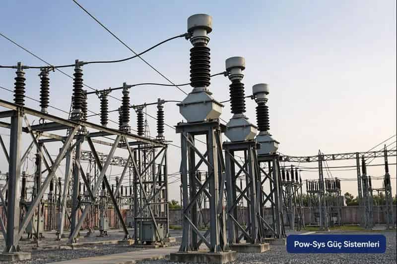
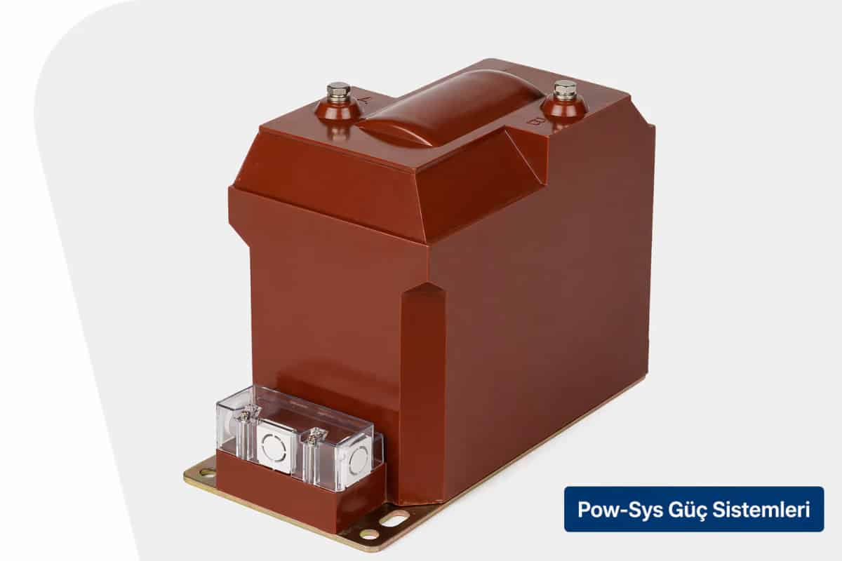
Voltage transformers appear in different types depending on the application. Inductive voltage transformers are used in medium-voltage switchgear and many conventional applications, while capacitive voltage transformers, or CVTs, become more common at very high voltage levels. CVT structures are used especially in high-voltage networks for measurement and protection purposes. This distinction affects not only the physical structure of the equipment but also accuracy, insulation behavior and system integration.
In the field, the terms voltage transformer and potential transformer are often used with the same meaning. Technically, both refer to the instrument transformer known as VT or PT. In many applications, this equipment may have one or more secondary windings, and different secondaries may be separated according to measurement, protection or auxiliary circuit requirements. Especially in MV switchgear, this structure enables both the protection relay and the measuring device side to use the same primary voltage information.
One of the most important points in voltage transformer connection is correct arrangement of the secondary circuit. The VT secondary circuit is grounded for safety, which provides safer operation for measuring devices and relays. While open-circuit risk is prominent in current transformers, the secondary of a voltage transformer must not be short-circuited. Therefore, terminal markings, fuse structure, grounding arrangement and relay-meter wiring must be checked carefully during connection.
Proper protection of the primary side of voltage transformers is also a separate topic. In practice, the VT circuit is protected by primary fuses and disconnector arrangements. Especially in metal-clad MV switchgear, the voltage transformer is often used in its own compartment and in a fused structure. This design helps protect the equipment during faults and makes maintenance work safer. For this reason, voltage transformer selection is not only a matter of ratio; it must be considered together with the protection architecture.
When selecting a voltage transformer, accuracy class, burden load, secondary voltage level, insulation class, mounting type and purpose of use must be evaluated together. A VT selected for measurement may not behave the same as a VT used for protection. In measurement-oriented applications, low voltage error is required, while in protection-oriented applications the operating conditions needed by the relay become more important. Therefore, looking only at the primary/secondary ratio is often not sufficient when making a selection.
In medium- and high-voltage installations, voltage transformers play a critical role in busbar voltage monitoring, energy metering, synchronization control, directional protection, undervoltage protection and frequency-based protection functions. If the voltage seen by the relay is not correct, protection logic may not produce the expected result no matter how correct the relay setting is. Therefore, the VT circuit is not a passive part of the protection system; it is one of the fundamental inputs that directly determines its performance.
From a maintenance perspective, cracks in the body, contamination on the resin surface, loose terminals, fuse condition, secondary circuit continuity and grounding connection must be checked regularly on voltage transformers. Especially in MV switchgear, a blown fuse, secondary circuit interruption or incorrect wiring can cause loss of voltage information even without equipment failure. For this reason, voltage transformer maintenance should cover not only the equipment itself but also the connected measurement and protection chain.
In summary, a voltage transformer is one of the basic items of equipment that enables measurement and protection devices in high-voltage systems to operate with safe, accurate and standard voltage information. With its parallel connection structure, standard secondary voltages, measurement and protection use, and inductive or capacitive type options, it is among the indispensable components of modern power facilities. If MV/HV measurement circuits, relay voltage inputs, VT connections or in-switchgear suitability need to be evaluated together in your facility, it is possible to proceed in an integrated way with HV/MV testing, maintenance and repair, LV/MV/HV project design and consultancy and HV operation responsibility services.
Related Blog Posts
Related Services
Frequently Asked Questions
What is a voltage transformer?
A voltage transformer, also called a potential transformer, is an instrument transformer that converts high voltage values in electrical systems to a lower and safe level that measuring instruments and protection relays can use. Unlike a power transformer, its purpose is not to transfer energy but to carry voltage information to the secondary circuit accurately and safely, while also isolating the secondary circuit from the primary side. It produces a reliable voltage reference for voltmeters, meters, power quality analyzers, synchronization circuits and protection relays, so grid voltage is transmitted to devices in a controlled and standardized way instead of being applied to them directly. In technical literature the same equipment is known as a VT or PT, and it is one of the fundamental components of measurement and protection systems in medium- and high-voltage installations.
What does a voltage transformer do?
A voltage transformer reduces line voltage to a level suitable for meters, voltmeters, power quality analyzers, synchronization circuits and protection relays. Its job is more than simply lowering voltage: it produces a reliable voltage reference so that voltage information in the grid is transmitted to devices in a controlled and standardized way instead of being carried to them directly. This protects the connected devices and provides healthy data on the measurement and protection side. Because standard secondary values are used, meters and relays can be operated with the same logic at different primary voltage levels, which makes device selection, setting management and panel design more controlled. In medium- and high-voltage installations it also supports busbar voltage monitoring, energy metering, synchronization control and voltage-based protection functions such as undervoltage and frequency-based protection.
How does a voltage transformer work?
A voltage transformer operates on the conventional transformer principle, which is based on electromagnetic induction. The AC voltage applied to the primary winding creates a varying magnetic flux in the core, and this flux induces a lower voltage in the secondary winding. The basic relationship is that the secondary voltage is obtained from the primary voltage through a defined transformation ratio, so the low-voltage output accurately represents the high voltage on the line. Unlike a current transformer, which sits in series with the circuit, a voltage transformer is connected to the line in parallel, because the quantity being monitored is voltage rather than current. Many units have one or more secondary windings, and different secondaries can be separated according to measurement, protection or auxiliary circuit requirements, so relays and measuring devices use the same primary voltage information.
How is a voltage transformer connected to the circuit?
A voltage transformer is connected in parallel to the line, because its purpose is to monitor the voltage in the circuit and convert it to a safe value on the secondary side. Correct arrangement of the secondary circuit is one of the most important points in the connection: the VT secondary is grounded for safety, which provides safer operation for measuring devices and relays, and the secondary must never be short-circuited. Terminal markings, the fuse structure, the grounding arrangement and the relay and meter wiring must all be checked carefully during connection work. On the primary side, the VT circuit is protected in practice by primary fuses and disconnector arrangements, and in metal-clad medium-voltage switchgear the voltage transformer is often installed in its own compartment in a fused structure, which makes both fault protection and maintenance safer.
Is there a difference between a potential transformer and a voltage transformer?
No, in practice there is no difference. In the field, the terms voltage transformer and potential transformer are used with the same meaning, and both refer to the instrument transformer known in technical literature as a VT or PT. Whatever the name, the equipment does the same job: it converts high voltage in the system to a lower, safe and standard level for measuring instruments and protection relays, and it isolates the secondary circuit from the primary side. In many applications this equipment may have one or more secondary windings, and different secondaries may be separated according to measurement, protection or auxiliary circuit requirements. Especially in medium-voltage switchgear, this structure enables both the protection relay side and the measuring device side to use the same primary voltage information, regardless of which of the two names is used for the equipment.
Why is the secondary of a voltage transformer 100 V or similar values?
Standard secondary values such as 100 V, 110 V, 115 V or 120 V are commonly used so that measurement and protection devices can operate at standard and safe input levels. Thanks to this structure, meters and relays can be operated with the same logic at different primary voltage levels: whatever the primary voltage of the system is, the devices always see a familiar, low and safe voltage on their inputs. For example, a phase-to-phase or phase-to-earth voltage in a medium-voltage system is reduced by a voltage transformer with the proper ratio to a level readable by relays and measuring devices. This standardization makes device selection, setting management and panel design more controlled, because the same relay and meter families can be applied across installations with very different primary voltage levels.
What is the difference between a voltage transformer and a current transformer?
A voltage transformer converts voltage and is connected to the line in parallel, while a current transformer converts current and is connected in series. Both are instrument transformers, but their duties and connection methods are different, because the quantity each one monitors is different. The safety rules are also opposite in a practical sense: while open-circuit risk is the prominent concern in current transformers, the secondary of a voltage transformer must not be short-circuited. On the voltage side, the VT secondary circuit is grounded for safety and typically supplies meters, voltmeters, power quality analyzers, synchronization circuits and protection relays with a standard voltage reference. In medium- and high-voltage switchgear the two types work side by side, one feeding current information and the other voltage information to the same measurement and protection chain.
What is a capacitive voltage transformer?
A capacitive voltage transformer, also known as a CVT, is a voltage transformer type that becomes more common at very high voltage levels. While inductive voltage transformers are used in medium-voltage switchgear and many conventional applications, CVT structures are used especially in high-voltage networks for measurement and protection purposes. The choice between the inductive and capacitive type is not only a matter of physical construction: this distinction affects the accuracy of the equipment, its insulation behavior and how it integrates with the rest of the system. In other words, both types perform the same fundamental duty of reducing high voltage to a safe, standard secondary level for relays and measuring devices, but the capacitive design is the option that suits the requirements of very high voltage networks, where it delivers the voltage reference needed by measurement and protection systems.
What should be considered when selecting a voltage transformer?
When selecting a voltage transformer, the accuracy class, burden load, primary-secondary ratio, secondary voltage level, insulation class, mounting type and purpose of use must be evaluated together. Looking only at the primary/secondary ratio is often not sufficient. A VT selected for measurement may not behave the same as a VT used for protection: measurement-oriented applications require low voltage error, while in protection-oriented applications the operating conditions needed by the relay become more important. The selection should also be considered together with the protection architecture, because in practice the VT circuit is protected by primary fuses and disconnector arrangements, and in metal-clad medium-voltage switchgear the voltage transformer is often installed in its own fused compartment. Evaluating all of these criteria as a whole ensures the equipment supports both accurate metering and reliable relay operation.
Which safety points are important for a voltage transformer?
The most important safety points concern the secondary circuit and the primary protection. The VT secondary circuit is grounded for safety, which provides safer operation for measuring devices and relays, and the secondary of a voltage transformer must never be short-circuited. Terminal markings, connection polarity, the fuse structure, the grounding arrangement and the relay and meter wiring must be checked carefully during connection. On the primary side, the circuit is protected by primary fuses and disconnector arrangements, and in metal-clad medium-voltage switchgear the VT is often used in its own fused compartment. From a maintenance perspective, cracks in the body, contamination on the resin surface, loose terminals, fuse condition, secondary circuit continuity and the grounding connection must be checked regularly, because a blown fuse or a secondary interruption can cause loss of voltage information even without an equipment failure.
Where are voltage transformers used?
Voltage transformers are used wherever measurement and protection devices in medium- and high-voltage installations need safe and accurate voltage information. They play a critical role in busbar voltage monitoring, energy metering, synchronization control, directional protection, undervoltage protection and frequency-based protection functions. In medium-voltage switchgear they typically supply voltmeters, meters, power quality analyzers, synchronization circuits and protection relays, often through one or more secondary windings separated according to measurement, protection or auxiliary circuit requirements. Their role in protection is especially important: if the voltage seen by the relay is not correct, the protection logic may not produce the expected result no matter how correct the relay setting is. For this reason the VT circuit is not a passive part of the protection system but one of the fundamental inputs that directly determines its performance.